Tekpower TP1503C: Difference between revisions
Jump to navigation
Jump to search
(Created page with "Category:Tools ''This page is currently under construction.'' thumb | right | Front of the Tekpower TP1503C power supply ==Description== Th...") |
No edit summary |
||
| (One intermediate revision by the same user not shown) | |||
| Line 20: | Line 20: | ||
==Tips & Tricks== | ==Tips & Tricks== | ||
*Conduct a continuity check between the positive and negative/ground connections on your circuit with a digital multimeter ''before'' connecting to the power supply. This is to ensure | *Conduct a continuity check between the positive and negative/ground connections on your circuit with a digital multimeter ''before'' connecting to the power supply. This is to ensure there is not a short-circuit connection. | ||
*Disconnect the positive (+) test lead to remove power from the circuit quickly. Turning off the power supply will also work but generally takes longer to remove power from the load or circuit. | *Disconnect the positive (+) test lead to remove power from the circuit quickly. Turning off the power supply will also work but generally takes longer to remove power from the load or circuit. | ||
*Use a black test lead for the negative/ground (-) connection and a red test lead for the positive (+) connection to reduce the chance of mixing the wires up. | *Use a black test lead for the negative/ground (-) connection and a red test lead for the positive (+) connection to reduce the chance of mixing the wires up. | ||
*Generally speaking, it is good practice to connect the negative/ground first, then connect the positive test lead to the circuit (leaving the positive (+) terminal on the power supply disconnected). When the circuit is ready to be powered on, insert the test clip lead into the positive (+) connection on the power supply to complete the circuit. | |||
==Manuals== | ==Manuals== | ||
Latest revision as of 21:10, 30 September 2019
This page is currently under construction.
Description
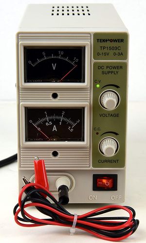
The Tekpower TP1503C is a direct-current (DC) power supply. This device can supply a constant voltage or constant current to an electrical load, and is useful for powering a range of devices. The TP1503C can supply a range of voltages from 0V to +15V, at up to 3A current.
Training
Operation
- Ensure the power supply is powered off.
- Connect a banana-to-alligator clip test lead to the ground connection in the circuit and the negative (-) connector on the power supply. Leave the positive (+) connection disconnected.
- Turn both voltage and current knobs counterclockwise to their minimum values.
- Turn on the power supply and set the voltage to the desired value using the voltage knob.
- When a load is connected to the power supply, it operates in either C.V. (constant voltage) mode or C.C. (constant current) mode. When the supply is in C.V. mode, it supplies a constant voltage and varies the current depending on the load. When in C.C. mode, the power supply is providing the maximum amount of current allowed by the current setting (knob), while the voltage varies. C.C. mode is essentially a current limiter. These modes are indicated by their respective LEDs on the front panel of the power supply.
- If the power supply reaches C.C. mode before reaching the desired voltage, turn the current knob clockwise slowly until the supply goes back to C.V. mode.
- After completing a continuity check on the circuit (more under Tips & Tricks), connect the circuit positive to the power supply positive (+) connection.
- If the power supply voltage drops and starts to operate in C.C. mode, the circuit is consuming more power than the power supply can deliver. Turn the current knob clockwise until the supply goes back to C.V. mode.
When finishing up, be sure to:
- Disconnect all test clip leads to the power supply.
- Turn off the power supply and remove the plug from the wall.
Tips & Tricks
- Conduct a continuity check between the positive and negative/ground connections on your circuit with a digital multimeter before connecting to the power supply. This is to ensure there is not a short-circuit connection.
- Disconnect the positive (+) test lead to remove power from the circuit quickly. Turning off the power supply will also work but generally takes longer to remove power from the load or circuit.
- Use a black test lead for the negative/ground (-) connection and a red test lead for the positive (+) connection to reduce the chance of mixing the wires up.
- Generally speaking, it is good practice to connect the negative/ground first, then connect the positive test lead to the circuit (leaving the positive (+) terminal on the power supply disconnected). When the circuit is ready to be powered on, insert the test clip lead into the positive (+) connection on the power supply to complete the circuit.
Manuals
Accessories
If you are looking for something on this list, and you cannot find it in the room, tell a manager. We likely have more stock in storage.
- Banana-to-alligator clip test leads
