Learn to Solder Kit
Overview
The Learn to Solder Kit is a bag of electronics that, when combined with this page, acts as a good first soldering project.

What's in the bag

The kit contains:
- A Printed Circuit Board (PCB)
- An LED
- A 220 Ohm (Ω) Resistor
- A push button
- A battery holder
- A battery (CR2032)
Tools Required
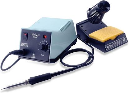
Weller WES51 Soldering Station*
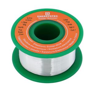
Solder
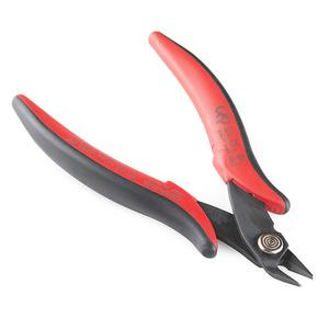
Flush Cutters
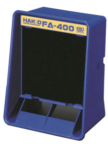
Filter Fan


Soldering Tips

- Complete the training on ELMS!
- Soldering is done by heating up the pins/pads, then melting the solder onto them to make a connection. Melting solder onto cold component leads will make bad connections.
- Clean the tip of the iron often with either abrasive metal or a sponge wet with distilled water. Melt some solder onto the tip after cleaning.
- Keep the extractor fan as close as is comfortable to the part you're soldering. It will keep the lead out of your lungs.
- If the solder isn't melting when you touch it to the iron, increase the temperature. (700°F is recommended)
- Use as little solder as is necessary to make the connection. This will make it easier to correct mistakes and will cause less shorts.
- If the solder isn't adhering to the pins/pads, try adding flux.
Tutorial
Setup
Heat the soldering iron up to 700°F and wait about 30 seconds for it to heat up. Turn on the filter fan so that you don't breathe in the fumes.
Get the items out of the bag.
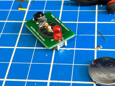
Step 1: The Resistor
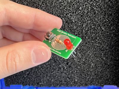
The resistor is the small component with long leads and stripes on it.
It belongs in the metal shell logo on the PCB. Orientation does not matter for this component.
Bend the leads of the resistor inwards. They should be about the same distance apart as the holes in the PCB.
Slide the resistor into its holes on the PCB.
When it is all the way in, flip the board and bend the leads outward so that the resistor can't fall back out.
Then, solder the connections and snip the rest of the leads.
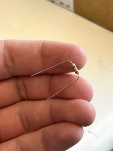
Bend the leads of the resistor
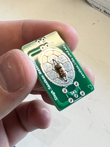
Insert the resistor into the holes on the PCB.
On the opposite side of the board, bend the leads of the resistor outwards so that it can't move.
Solder the leads to the board
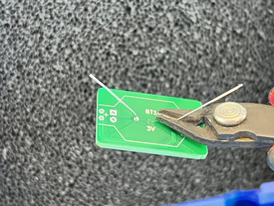
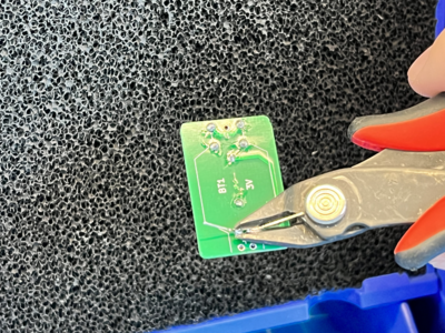
Snip the excess with the flush cutters.


Step 2: The Switch
The switch is the square component with a button and four pins.
Its footprint on the circuit board is marked by a "SW1".
With the legs facing out to the sides, simply put the legs through the holes.
When it is pushed all the way in, it should be held in with just tension.
Flip the board and solder all four legs. No need to snip anything yet.
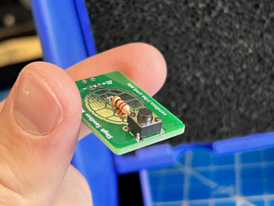
Place the switch
Solder the legs


Step 3: The LED
The LED is the component with the color plastic top and two legs.
One leg is longer than the other, this is the positive (+) leg. Orientation does matter for this component.
Its place on the PCB is marked with a - and a + (Long Leg). Place the LED into its correct holes.
Flip the board, bend the leads, and solder them as before.
Snip the excess as before.
Confirm that the short leg goes in the - hole and the long leg goes in the + hole.
Slide it in
Bend the leads
Solder and snip


Step 4: The Battery Holder
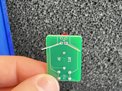
The battery holder is the beige component three leads. Orientation does matter for this component.
The lead by itself is the negative (-) lead, and the two leads on the other side are both positive (+).
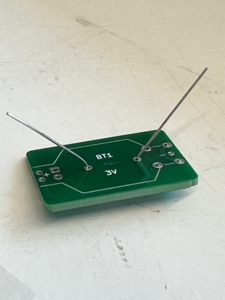
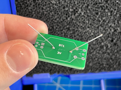
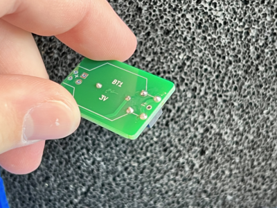
Its place on the PCB is marked on the backside of the PCB with a "BT1". It also indicates that the battery should be 3V (3 Volts).
Before placing the battery holder, use the flush cutters to snip any raised solder joints from the other components. Make the surface as flush as you can.
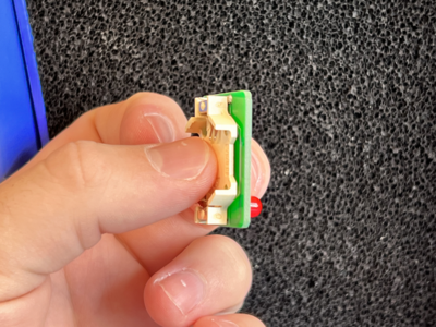
Once that's done, place the battery holder into its holes.
The positive leads can be soldered from the opposite side as normal, but the negative one cannot because of the button on the other side.
Solder the negative lead on the top. It is harder than soldering from the opposite side, but it doesn't need to be the best solder job in the world.
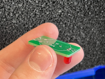
Snip the joints so that the surface is as flush as possible
Place the battery holder in (shortening the - lead if necessary)
Solder the + leads
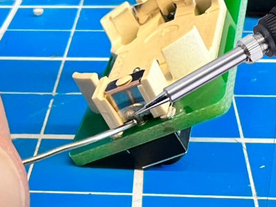
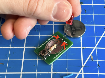
Solder the - lead from the top


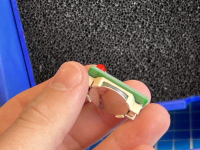
Step 5: The Battery
This one's easy. There's only one component left, and it's the battery.
The battery has a + and a - side. Recognize the + sign on the top of the battery.
Place the battery in the holder, + side up.
Place the battery in the holder

Finish!
Congratulations! You've finished your first soldering project! Press the button, and the LED should light up!